Engineering, 06.06.2020 02:04 sascsl7973
Explain the change in the flow pattern pressure distribution and the lift and drag coefficient for an aerofoil as its angle of attack is increased up to the stall.
It is assumed that for a given angle of incidence α (angle of attack), the lift and drag forces that act on an aerofoil are proportional to the dynamic pressure and the plan area S.
Formula for lift (L) and Drag (D) is
L = CL ½?v^2S and D = CD½ ?v^2S where CL = lift coefficient,
CD = Drag coefficient
S = Plan Area (m)
v = air speed (m/s)
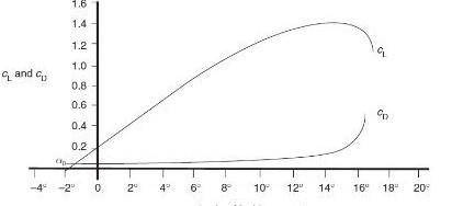
The graph below present 'variation of lift and drag coefficient versus angle of incidence α' (angle of attack) where plan area is 60m2 and air speed is 500 km/h.
•TASK 2.7:
From the graph above deduce the data for CL and CD (approx.) when angle of attack is 6ᵒ, and 14ᵒ
Your task is to:
• find the lift and drag forces for each case given above
• with aid of sketches / diagrams, explain:
a. how pressure distribution occurs on aerofoil (in each case)
b. how the air speed can be affected by changing the flow pattern pressure distribution, the lift coefficient and drag coefficient.
c. explain from your result under which condition(s) can an aircraft can be stalled
Answers: 1
Another question on Engineering
Engineering, 04.07.2019 18:10
The drive force for diffusion is 7 fick's first law can be used to solve the non-steady state diffusion. a)-true b)-false
Answers: 1
Engineering, 04.07.2019 18:10
Burgers vector is generally parallel to the dislocation line. a)-true b)-false
Answers: 2
Engineering, 04.07.2019 18:20
How much power could a wind turbine produce if it had the following specifications? cp = 0.45 -d=1.2kg/m3 d=50m v 5m/s
Answers: 2
Engineering, 04.07.2019 19:20
Apiping systems consists of 6 m of 6-std type k and 12 m of 4-std type k, both drawn copper tubing. the system conveys ethylene glycol at a rate of 0.013 m3/s. the pressure drop across the system is to be calculated. there are two 90° elbows in the 6-in pipe, a reduction from the 6-in pipe to the 4-in pipe and four 90° elbows in the 4-in pipe. all fittings are soldered (same as flanged) and regular. the inlet and outlet of the system are at the same height.
Answers: 1
You know the right answer?
Explain the change in the flow pattern pressure distribution and the lift and drag coefficient for a...
Questions

History, 04.05.2020 23:33

Mathematics, 04.05.2020 23:33


Mathematics, 04.05.2020 23:33

Mathematics, 04.05.2020 23:33
History, 04.05.2020 23:34
History, 04.05.2020 23:34
English, 04.05.2020 23:34
History, 04.05.2020 23:34
Mathematics, 04.05.2020 23:34